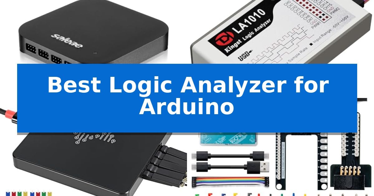
Debugging embedded systems often requires more than just a multimeter when signals become complex. A reliable logic analyzer allows you to visualize digital communication between your microcontroller and sensors, making it an essential tool for any serious developer. Finding the Best Logic Analyzer for Arduino involves balancing channel count, sampling rate, and software compatibility to ensure your debugging workflow remains efficient.
Whether you are troubleshooting a simple I2C sensor or analyzing high-speed SPI traffic, the right hardware can save hours of frustration. We have evaluated several popular models to help you identify which device aligns with your specific technical requirements and project scale, ensuring you have the visibility needed to resolve communication errors quickly.
You may also want to compare Best Logic Analyzer, Best Logging Multimeter, and Best Lockly Smart Lock.
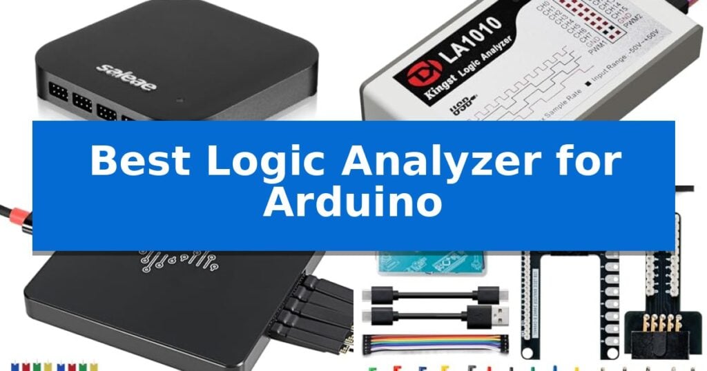
Best Logic Analyzer for Arduino
Quick Comparison
| Product | Best For | Key Strength | Score |
|---|---|---|---|
| Saleae Logic Pro 16 Logic Analyzer | Best Overall | 16-channel multi-use digital and analog inputs | 4.9 |
| Innomaker LA1010 USB Logic Analyzer | High Speed 16-Channel Debugging | 16 input channels for simultaneous monitoring of complex digital buses. | 4.3 |
| VQP DSLogic Plus Logic Analyzer | Deep Memory Protocol Analysis | Dual-mode support for both real-time streaming and high-speed buffered capture. | 4.9 |
| Lonely Binary Logic Analyzer Kit | Complete Prototyping Starter Set | 8-channel analysis at 24MHz for protocol debugging | 4.3 |
| HiLetgo USB Logic Analyzer | Budget Friendly Entry Pick | 8-channel monitoring for simultaneous signal analysis | 4.4 |
How We Chose
- Channel count and input flexibility for complex multi-sensor setups.
- Maximum sampling rate and memory depth to capture high-speed data transitions.
- Cross-platform software support for Windows, macOS, and Linux environments.
- Protocol decoding capabilities for standard interfaces like UART, SPI, and I2C.
- Physical connectivity options, including breadboard compatibility and test clip accessories.
1 Saleae Logic Pro 16 Logic Analyzer — Professional Grade Signal Analysis
The Saleae Logic Pro 16 Logic Analyzer distinguishes itself through its versatile architecture, offering 16 channels that function as either digital or analog inputs. This flexibility allows users to monitor complex signal interactions on an Arduino or other microcontroller platforms without needing separate instruments for different signal types.
Designed for high-performance signal analysis, this device supports a digital sample rate up to 500 MS/s and an analog sample rate up to 50 MS/s. It leverages the host computer's memory via a USB 3.0 connection, enabling the capture of massive datasets—up to 10 billion digital samples—which is essential for debugging intermittent communication issues in protocols like SPI and I2C.
The unit is built for cross-platform compatibility, functioning seamlessly across Windows, Mac, and Linux environments. Its compact, ultra-portable design ensures it fits easily into a workspace, while the software interface simplifies the process of decoding over 23 protocols, reducing the time spent manually interpreting signal transitions.
While the device excels in data density and protocol support, it relies entirely on the host PC's resources for data processing and storage. Users should ensure their workstation meets the necessary USB 3.0 requirements to fully utilize the high sampling rates, as performance is tethered to the connected computer's capabilities.
Best for: Engineers and hobbyists requiring high-speed, multi-channel signal analysis for complex protocol debugging on Arduino and similar embedded systems.
Skip if: Users who only require basic, low-speed digital monitoring and prefer a standalone, screen-integrated oscilloscope or a lower-cost, single-purpose logic probe.
PROS
- 16-channel multi-use digital and analog inputs
- Comprehensive protocol decoding for SPI, I2C, and 23+ others
- High-speed USB 3.0 interface for massive data capture
- Broad cross-platform support for Windows, Mac, and Linux
CONS
- Dependent on host PC memory and processing power
- Requires USB 3.0 connectivity for maximum sampling performance
2 Innomaker LA1010 USB Logic Analyzer — High Speed 16-Channel Debugging
Debugging complex digital communication requires more than just a multimeter; it demands a window into the timing and state of your signals. The Innomaker LA1010 USB Logic Analyzer provides this visibility by offering 16 input channels capable of a 100MHz sampling rate, allowing you to capture and visualize high-speed digital waveforms directly on your computer screen.
Designed for versatility, this analyzer excels at decoding over 30 standard communication protocols, including I2C, SPI, UART, and CAN. By translating raw electrical transitions into human-readable data, it significantly reduces the time spent troubleshooting embedded systems, whether you are working with microcontrollers, ARM processors, or FPGA development boards.
The hardware features a portable, low-power design that connects seamlessly via USB. Compatibility is a primary strength, as the device supports Windows, macOS, and Linux with auto-installing drivers that eliminate the need for complex configuration. This plug-and-play approach ensures that you can focus on your circuit analysis rather than software setup.
While it serves as a robust tool for long-term signal monitoring and digital circuit testing, its effectiveness is tied to the provided KingstVIS software. This software suite is essential for the real-time visualization and protocol extraction that makes the hardware useful for developers.
Best for: Embedded systems developers and hobbyists who need to debug multi-channel digital communication protocols like I2C, SPI, and UART on a PC.
Skip if: Users who require an integrated oscilloscope for viewing analog signal integrity or those who need a standalone handheld device without a PC connection.
PROS
- 16 input channels for simultaneous monitoring of complex digital buses.
- 100MHz sampling rate provides high-resolution data capture for digital signals.
- Cross-platform support with auto-installing drivers for Windows, macOS, and Linux.
- Protocol decoding for over 30 standards to simplify data extraction.
CONS
- PC-dependent operation requires the KingstVIS software for all data visualization and analysis.
- Digital-only signal capture lacks the analog measurement capabilities of an oscilloscope.
3 VQP DSLogic Plus Logic Analyzer — Deep Memory Protocol Analysis
Debugging complex embedded systems requires precise timing and deep visibility into signal transitions. The VQP DSLogic Plus Logic Analyzer provides this through its 16-channel dual-mode support, allowing users to switch between Stream mode for long-duration data capture and Buffer mode for high-speed sampling. This flexibility is essential for monitoring serial communication protocols like I2C, SPI, or UART common in microcontroller projects.
The device features a USB 2.0 Type-C interface and includes 256Mbits of on-board SDRAM memory, which facilitates robust data storage during high-frequency capture sessions. With a sampling rate of up to 400MHz, it offers the necessary bandwidth to observe rapid signal changes accurately. The inclusion of shielded wires and adjustable thresholds helps in maintaining signal integrity, ensuring that the captured waveforms remain clean and reliable for analysis.
Software integration is a core strength of this unit, as it maintains compatibility with Windows, macOS, and Linux. The platform supports nearly 100 protocol decoders, making it a versatile tool for developers working across different environments. Furthermore, the project is open-source on Github, providing transparency and potential for community-driven improvements or custom extensions.
When setting up a test bench, the VQP DSLogic Plus Logic Analyzer balances high-performance capture with practical connectivity. While it offers significant depth for protocol analysis, users should ensure their computer hardware supports the necessary USB throughput to maximize the 16G sample depth available in stream mode. It serves as a capable instrument for those needing to move beyond basic multimeter checks into full signal timing verification.
Best for: Engineers and hobbyists requiring deep memory protocol analysis and high-speed signal capture for embedded system development.
Skip if: Users who only need basic voltage or continuity checks and do not require multi-channel protocol decoding or high-frequency waveform analysis.
PROS
- Dual-mode support for both real-time streaming and high-speed buffered capture.
- 16-channel input allows for simultaneous monitoring of multiple communication lines.
- Open-source software support with nearly 100 protocol decoders included.
- Shielded wires and adjustable thresholds for improved signal integrity.
CONS
- USB 2.0 interface may limit data transfer rates compared to newer standards.
- Requires PC-based software for all data visualization and analysis.
4 Lonely Binary Logic Analyzer Kit — Complete Prototyping Starter Set
Debugging complex microcontroller communication requires reliable visibility into digital signals. The Lonely Binary Logic Analyzer Kit provides this through its high-speed 8-channel analysis, capable of capturing data at up to 24MHz. This allows for the precise monitoring of I2C, SPI, and UART protocols, making it a functional tool for those working on advanced Arduino-based projects.
The kit is designed for versatility in prototyping environments. It includes a logic level expansion board that breaks out all 8 channels to 2.54mm male pins and pads, facilitating secure connections with alligator clips. For breadboard-centric workflows, the included logic level breadboard adapter provides direct, organized access to all channels, reducing the clutter often associated with manual jumper wire setups.
Compatibility is addressed through the inclusion of both USB-A and USB-C cables, ensuring the device connects to a wide range of modern and legacy hardware. The system is designed for plug-and-play operation across Windows, Mac, Linux, and Ubuntu, minimizing the setup time required before signal capture can begin.
This analyzer is a comprehensive starter set that balances essential debugging capabilities with practical accessories. By providing the base module alongside specific adapters and a storage case, it offers a complete solution for developers who need to verify signal integrity during the development of embedded systems.
Best for: Developers and students needing an affordable, multi-channel tool for debugging common communication protocols on Arduino and other microcontrollers.
Skip if: Users requiring professional-grade features like deep memory buffers, higher sampling rates for high-speed digital logic, or advanced protocol decoding software may find this entry-level kit limiting.
PROS
- 8-channel analysis at 24MHz for protocol debugging
- Includes breadboard and expansion adapters for flexible connections
- Supports USB-A and USB-C connectivity for broad compatibility
- Comes with a storage case and essential test clips
CONS
- Limited to 24MHz sampling rate
- Lacks advanced features found in high-end professional logic analyzers
5 HiLetgo USB Logic Analyzer — Budget Friendly Entry Pick
Debugging serial communication protocols like UART, IIC, or SPI on an Arduino project requires visibility into signal timing and state changes. The HiLetgo USB Logic Analyzer provides this insight through an 8-channel interface, allowing developers to monitor multiple signals simultaneously at a sampling rate of up to 24 MHz.
This device is built for versatility in digital signal analysis, supporting a wide range of sampling frequencies from 24 MHz down to 25 KHz. This flexibility ensures that users can capture both high-speed data bursts and slower control signals, making it a practical tool for verifying communication between an Arduino and various sensors or peripherals.
Designed with an input voltage range of -0.5V to 5.25V, the analyzer is well-suited for standard 5V and 3.3V logic levels commonly found in hobbyist electronics. The input impedance of approximately 1Mohm || 10pF minimizes the impact on the circuit being tested, helping to maintain signal integrity during the debugging process.
The unit features a compact form factor and includes an EMI ferrite ring on the USB cable to assist with signal stability. By providing a clear visual representation of logic states, it helps identify timing errors or protocol mismatches that are otherwise invisible during standard code execution.
Best for: Hobbyists and students needing an affordable, portable tool for debugging common serial protocols on 5V or 3.3V microcontroller projects.
Skip if: Users requiring advanced features like deep buffer memory, analog signal visualization, or high-speed sampling rates exceeding 24 MHz should look for professional-grade benchtop equipment.
PROS
- 8-channel monitoring for simultaneous signal analysis
- Wide sampling rate range up to 24 MHz
- Compact and portable design for benchtop use
- Compatible with standard logic levels used in Arduino projects
CONS
- Limited sampling rate compared to professional high-speed analyzers
- Lacks analog signal capture capabilities
Best Logic Analyzer for Arduino Buying Guide
Understanding Sampling Rates and Bandwidth
The sampling rate is the frequency at which the analyzer captures the state of your digital lines. For most Arduino-based projects, a device capable of 24MHz is sufficient for standard I2C or UART communication. However, if you are working with high-speed SPI or custom parallel interfaces, you may require a device that supports higher sampling rates to avoid aliasing and ensure signal integrity.
It is important to note that bandwidth is distinct from the sampling rate. While the sampling rate determines how often the signal is read, the bandwidth relates to the maximum frequency the input circuitry can handle without significant attenuation. Always check the manufacturer's specifications to ensure the device can accurately represent the rise and fall times of your specific signals.
The Importance of Protocol Decoding
A logic analyzer is only as useful as the software that interprets the captured data. Modern analyzers often come with protocol decoding software that translates raw binary waveforms into human-readable text. This feature is vital for debugging communication errors, as it allows you to see exactly what data packets are being sent and received between your Arduino and peripheral devices.
Look for software that supports a wide range of protocols, including I2C, SPI, and UART, as these are the most common interfaces used in hobbyist and professional electronics. Some advanced software suites also allow for custom protocol definitions, which can be a significant advantage if you are working with proprietary or non-standard communication schemes.
Memory Depth and Stream Mode
When capturing long sequences of data, memory depth becomes a critical factor. A device with limited onboard memory will stop recording once its buffer is full, which can cause you to miss intermittent bugs that occur after a long period of operation. High-end analyzers often use your PC's RAM via USB 3.0 to provide virtually unlimited capture time.
Some devices offer a stream mode that transfers data to your computer in real-time. This is particularly useful for long-term monitoring where you need to track signal behavior over several minutes or hours. If your debugging process involves capturing complex boot sequences or extended data logs, prioritize models that offer robust streaming capabilities.
Connectivity and Physical Form Factor
The physical design of the analyzer dictates how easily it integrates into your existing setup. Devices that include breadboard adapters or high-quality test clips allow for quick connections without the need for custom wiring. Consider the physical size of the unit, especially if your workspace is limited or if you need a portable solution for field testing.
Check the input voltage range to ensure it is compatible with your project's logic levels. Most Arduino boards operate at 5V or 3.3V, and using an analyzer that cannot handle these levels could result in damage to either the device or your microcontroller. Always verify that the input impedance is high enough to avoid loading your circuit and distorting the signals you are trying to measure.
Software Compatibility and Drivers
Before making a purchase, verify that the analyzer's software is compatible with your operating system. While most modern logic analyzers support Windows, macOS, and Linux, the ease of driver installation can vary significantly. Some devices are plug-and-play, while others may require specific configuration or manual driver management.
Open-source software support is another factor to consider. Tools that are compatible with open-source platforms often have larger community support, providing access to a wider variety of protocol decoders and troubleshooting resources. This can be a significant benefit if you encounter issues or need to extend the functionality of your analyzer for specialized tasks.
Frequently Asked Questions
Can I use a logic analyzer to debug analog signals?
While logic analyzers are primarily designed for digital signals, some professional-grade models offer hybrid inputs that can capture both digital states and analog voltage levels. Always check the specific product features to see if analog sampling is supported.
What is the difference between a logic analyzer and an oscilloscope?
An oscilloscope is designed to show the exact voltage waveform over time, which is useful for checking signal integrity and noise. A logic analyzer is designed to capture and decode digital data streams, making it better for analyzing communication protocols.
Do I need a USB 3.0 port for all logic analyzers?
Not necessarily. While USB 3.0 is required for high-speed, high-bandwidth data transfer in professional models, many entry-level analyzers operate effectively over USB 2.0. Check the requirements of the specific model you are considering.
Are logic analyzer test clips universal?
Most test clips use standard pin spacing, but the quality and grip strength can vary. If you are working with very small components, look for high-quality, fine-pitch clips to ensure a secure connection without shorting adjacent pins.
How many channels do I need for Arduino debugging?
For most basic Arduino projects, 8 channels are sufficient to monitor common protocols like SPI or I2C. If you are working with parallel buses or complex multi-device systems, a 16-channel analyzer will provide the necessary overhead.
Conclusion: Our Top Pick
For those requiring a professional-grade tool with high sampling rates and versatile input capabilities, the Saleae Logic Pro 16 Logic Analyzer stands out as the most capable option. Its ability to handle both digital and analog signals, combined with its robust software, makes it an excellent investment for complex development projects.
While the higher price point reflects its advanced feature set, the time saved during debugging and the clarity of data provided often justify the cost for serious developers. If your work involves frequent protocol analysis and high-speed signal monitoring, this device provides the reliability and performance needed to streamline your Arduino development process.